Simple diy LED light bulb
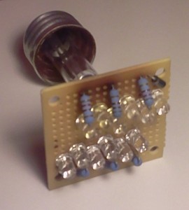
 I’ve been wanting to get my hands on an LED light bulb for some time now. They’re still rather expensive though, so for most people they don’t seem “worth it” when CFL’s are much cheaper and still pretty low on the power consumption scale. So rather than going out and buying a commercial LED lightbulb, I decided to make my own. The cost isn’t substantially lower especially given the final output power, but you get the enjoyment of being able to say “Hey, look at this cool thing I made!”. Having a power saving and virtually immortal light afterwards is just a bonus.
This bulb could be made in an afternoon, you only need a few parts and tools:
- Small perfboard
- Light bulb socket base
- 12x identical LED’s
- 2x 1N4004 diodes
- 6x 8.2K Ohm, 1 Watt Resistors
- Soldering iron + solder
You can get the perfboard at Radio Shack or similar electronics outlet. The bulb socket base can be acquired by breaking it off a dead incandescent bulb, just be very careful doing this. I got the rest of the parts from mouser.com. The total cost for me was about $7.
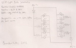
The electrical design is very simple. The 1N4004 diodes on either side of the circuit function as half wave rectifiers for the incoming AC power, and as a reverse current protector to keep the LED’s from frying when the cycle is reversed. The current is then lowered to usable levels by the resistors and passed to the LED’s. Since the circuit doesn’t have a filter capacitor to continually feed the LED’s, each side only remains illuminated for half of the AC cycle. Alternating illumination gives the appearance of steady light, even though each side is turning on and off 30 times per second with a 60hz input signal. Here’s a schematic that should better illustrate what is going on:
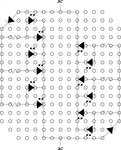
This is the layout I came up with for the small perfboard I got from RadioShack. It’s the first one I came up with, so there very well might be a better arrangement that could fit more LED’s. Feel free to experiment.
LED’s certainly are more efficient than incandescent bulbs, but this particular circuit is not the most ideal design. It uses few inexpensive parts, but it could be improved on. Ideally there would be some regulator circuit to lower current to usable levels, instead of the resistors in place here that just drop the power as heat. It’s not much heat, but the point is that it could produce almost no heat with a more efficient (but slightly more complex and expensive) design.
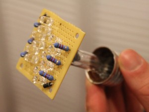
After about 9 months of being on for 12 hours a day you can see that the board around the resistors has started to turn brown from the heat they put off. While this isn’t enough heat to be dangerous in terms of a fire, you definitely don’t want to touch them (let’s just ignore the fact that there’s 120v AC running around there…). They operate well under their 1W maximum dissipation. If my calculations are correct (and I’m no electrical engineer), the whole contraption consumes just over a watt of power (and if I’m wrong, it’s probably not more than 3 watts).
Update: A generous reader provided me with a video of the LED bulb circuit being simulated so that you can see its operation greatly slowed down.
He also provided the source file used to create this video for a circuit simulator called Livewire. In addition I have included a circuit file for LTspice IV, a free circuit simulator. You can download all of these files here.


Hi Mr. Foltz,
How about 220V AC line what would be the correct Resistor value?
is 15K ok? I’m not sure… BTW thanks for putting this post!!
15K should be OK, but you will need to use 2 watt resistors. They will generate nearly twice as much heat since they are dropping twice the voltage.
Will Diode 1N2004 work for 230v supply ?
I couldn’t find much on that specific diode. What I did find would suggest that yes, the 1N2004 diode would be fine. If you meant the 1N4002 (more common) diode, this one will NOT be fine. You would need a 1N4004 or higher diode for that voltage.